MS Angle Size Chart PDF - Complete Guide & Free Download
Comprehensive MS angle size chart with dimensions, weights, and specifications. Essential resource for engineers, students, and construction professionals. Download the complete PDF guide for offline reference.
Table of Contents
Introduction to MS Angles
Mild Steel (MS) angles, also known as angle iron or L-shaped steel, are fundamental structural components used extensively in construction, engineering, and manufacturing industries. These versatile steel profiles provide excellent structural support and are characterized by their L-shaped cross-section.
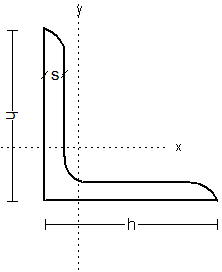
Figure 1: Steel Angle Cross-Section Diagram
Key Characteristics:
- Material: Mild steel with carbon content typically between 0.15-0.25%
- Shape: L-shaped profile with two perpendicular legs
- Types: Equal leg angles and unequal leg angles
- Standards: Manufactured according to IS 2062, ASTM A36, EN 10025
- Finish: Hot rolled, galvanized, or painted
Standard MS Angle Sizes
MS angles are available in a wide range of standard sizes to meet various structural requirements. The size designation typically follows the format: Length × Width × Thickness (in mm or inches).
Size Designation Format:
- Metric System: 50 × 50 × 6 mm (Length × Width × Thickness)
- Imperial System: 2" × 2" × 1/4" (Length × Width × Thickness)
- Weight Specification: Often expressed as kg/m or lb/ft
Equal Leg Angles Chart
Equal leg angles have both legs of equal length, making them ideal for symmetric loading conditions. They are commonly used in structural frameworks, bracing, and general construction applications.
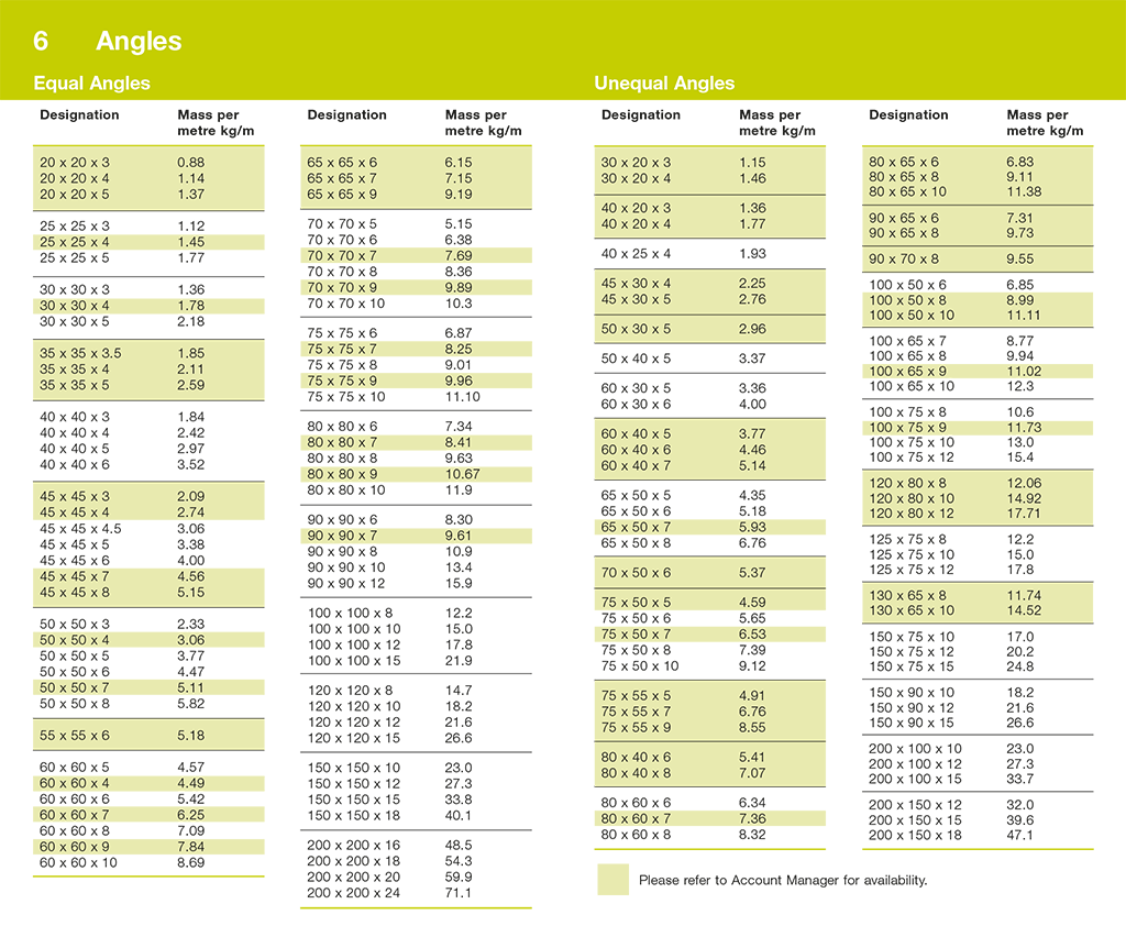
Figure 2: Comprehensive Steel Angle Size Chart
Equal Leg Angles - Metric Sizes
| Size (mm) | Leg Length A (mm) | Leg Length B (mm) | Thickness (mm) | Weight (kg/m) | Cross-Section Area (cm²) | Common Applications |
|---|---|---|---|---|---|---|
| 20×20×3 | 20 | 20 | 3 | 0.90 | 1.14 | Light framing, brackets |
| 25×25×3 | 25 | 25 | 3 | 1.10 | 1.42 | Small structures, supports |
| 25×25×4 | 25 | 25 | 4 | 1.45 | 1.85 | Reinforcement, brackets |
| 30×30×3 | 30 | 30 | 3 | 1.36 | 1.74 | Framework, bracing |
| 30×30×4 | 30 | 30 | 4 | 1.78 | 2.27 | Structural supports |
| 40×40×3 | 40 | 40 | 3 | 1.84 | 2.35 | Medium frameworks |
| 40×40×4 | 40 | 40 | 4 | 2.42 | 3.08 | Structural beams |
| 40×40×5 | 40 | 40 | 5 | 2.97 | 3.79 | Heavy duty supports |
| 50×50×4 | 50 | 50 | 4 | 3.06 | 3.89 | Building frameworks |
| 50×50×5 | 50 | 50 | 5 | 3.77 | 4.80 | Structural applications |
| 50×50×6 | 50 | 50 | 6 | 4.47 | 5.69 | Heavy construction |
| 60×60×5 | 60 | 60 | 5 | 4.57 | 5.82 | Industrial structures |
| 60×60×6 | 60 | 60 | 6 | 5.42 | 6.91 | Building construction |
| 60×60×8 | 60 | 60 | 8 | 7.09 | 9.03 | Heavy frameworks |
| 70×70×5 | 70 | 70 | 5 | 5.38 | 6.85 | Structural beams |
| 70×70×6 | 70 | 70 | 6 | 6.38 | 8.13 | Construction frameworks |
| 75×75×5 | 75 | 75 | 5 | 5.78 | 7.37 | Medium construction |
| 75×75×6 | 75 | 75 | 6 | 6.85 | 8.73 | Structural supports |
| 75×75×8 | 75 | 75 | 8 | 8.95 | 11.40 | Heavy duty applications |
| 80×80×6 | 80 | 80 | 6 | 7.34 | 9.35 | Industrial construction |
| 80×80×8 | 80 | 80 | 8 | 9.63 | 12.27 | Heavy structures |
| 90×90×6 | 90 | 90 | 6 | 8.22 | 10.47 | Building construction |
| 90×90×8 | 90 | 90 | 8 | 10.83 | 13.80 | Structural frameworks |
| 90×90×10 | 90 | 90 | 10 | 13.38 | 17.05 | Heavy construction |
| 100×100×6 | 100 | 100 | 6 | 9.11 | 11.60 | Large structures |
| 100×100×8 | 100 | 100 | 8 | 12.02 | 15.31 | Industrial applications |
| 100×100×10 | 100 | 100 | 10 | 14.89 | 18.97 | Heavy duty construction |
| 120×120×8 | 120 | 120 | 8 | 14.70 | 18.72 | Large frameworks |
| 120×120×10 | 120 | 120 | 10 | 18.24 | 23.24 | Heavy construction |
| 120×120×12 | 120 | 120 | 12 | 21.73 | 27.68 | Industrial structures |
| 150×150×10 | 150 | 150 | 10 | 23.07 | 29.39 | Large buildings |
| 150×150×12 | 150 | 150 | 12 | 27.49 | 35.02 | Heavy industrial use |
| 150×150×15 | 150 | 150 | 15 | 33.93 | 43.23 | Major construction |
Unequal Leg Angles Chart
Unequal leg angles have legs of different lengths, providing asymmetric loading capabilities. They are ideal for applications where different load-bearing requirements exist along each axis.
Unequal Leg Angles - Metric Sizes
| Size (mm) | Leg A (mm) | Leg B (mm) | Thickness (mm) | Weight (kg/m) | Cross-Section Area (cm²) | Typical Applications |
|---|---|---|---|---|---|---|
| 40×25×4 | 40 | 25 | 4 | 1.93 | 2.46 | Window frames, door frames |
| 50×30×4 | 50 | 30 | 4 | 2.42 | 3.08 | Shelf brackets, supports |
| 50×30×5 | 50 | 30 | 5 | 2.97 | 3.78 | Structural connections |
| 60×40×5 | 60 | 40 | 5 | 3.77 | 4.80 | Building frameworks |
| 60×40×6 | 60 | 40 | 6 | 4.47 | 5.69 | Structural beams |
| 65×50×5 | 65 | 50 | 5 | 4.35 | 5.54 | Medium construction |
| 65×50×6 | 65 | 50 | 6 | 5.15 | 6.56 | Industrial applications |
| 75×50×6 | 75 | 50 | 6 | 5.72 | 7.29 | Structural supports |
| 75×50×8 | 75 | 50 | 8 | 7.52 | 9.58 | Heavy frameworks |
| 80×60×6 | 80 | 60 | 6 | 6.38 | 8.13 | Building construction |
| 80×60×8 | 80 | 60 | 8 | 8.41 | 10.72 | Structural applications |
| 100×65×7 | 100 | 65 | 7 | 8.77 | 11.17 | Large structures |
| 100×65×8 | 100 | 65 | 8 | 9.94 | 12.66 | Industrial construction |
| 100×75×8 | 100 | 75 | 8 | 10.83 | 13.80 | Heavy duty applications |
| 100×75×10 | 100 | 75 | 10 | 13.38 | 17.05 | Major construction |
| 125×75×8 | 125 | 75 | 8 | 12.27 | 15.64 | Large buildings |
| 125×75×10 | 125 | 75 | 10 | 15.21 | 19.38 | Heavy construction |
| 150×100×10 | 150 | 100 | 10 | 18.99 | 24.19 | Industrial structures |
| 150×100×12 | 150 | 100 | 12 | 22.69 | 28.91 | Heavy industrial use |
Weight Calculations & Formulas
Understanding how to calculate the weight of MS angles is crucial for structural design and material estimation. The weight calculation is based on the cross-sectional area and the density of steel.
Basic Weight Formula
Weight (kg/m) = Cross-sectional Area (cm²) × Density of Steel (kg/cm³) × 100
Where: Density of Steel = 0.00785 kg/cm³
Cross-Sectional Area Calculation
For equal leg angles:
Area = (A + B - t) × t
Where:
- A = Length of first leg (cm)
- B = Length of second leg (cm)
- t = Thickness (cm)
Weight Calculation Chart
Practical Calculation Examples
-
50×50×6 mm Equal Angle:
- Area = (5 + 5 - 0.6) × 0.6 = 5.64 cm²
- Weight = 5.64 × 0.785 = 4.43 kg/m
-
75×50×6 mm Unequal Angle:
- Area = (7.5 + 5 - 0.6) × 0.6 = 7.14 cm²
- Weight = 7.14 × 0.785 = 5.61 kg/m
Real-World Applications
MS angles are versatile structural components used across various industries and applications. Their L-shaped profile provides excellent strength-to-weight ratio and structural stability.
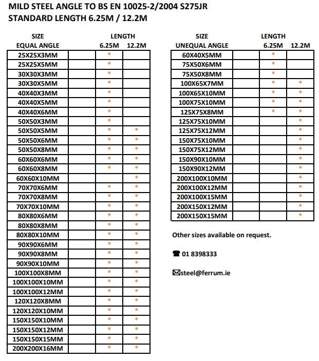
Figure 3: Various MS Angle Applications in Construction
Construction Industry
- Building Frameworks: Primary and secondary structural elements
- Roof Trusses: Supporting roof structures and loads
- Floor Joists: Supporting floor systems
- Stair Stringers: Supporting stair structures
- Bracing Systems: Lateral stability and wind load resistance
Industrial Applications
- Equipment Supports: Mounting heavy machinery and equipment
- Conveyor Systems: Framework for material handling systems
- Storage Racks: Warehouse and storage solutions
- Platform Structures: Access platforms and walkways
- Pipe Supports: Supporting piping systems
Architectural Applications
- Window Frames: Structural support for windows
- Door Frames: Frame construction for doors
- Decorative Elements: Architectural detailing
- Curtain Walls: Building envelope systems
- Canopies: Overhead protection structures
Manufacturing & Fabrication
- Machine Frames: Supporting manufacturing equipment
- Jigs and Fixtures: Assembly and welding fixtures
- Workbenches: Workshop and laboratory furniture
- Lifting Equipment: Cranes and hoisting systems
- Transportation: Truck bodies and trailer frames
Selection Guide & Tips
Selecting the right MS angle size depends on various factors including load requirements, span length, deflection limits, and economic considerations.
Key Selection Factors
-
Load Requirements:
- Dead loads (permanent loads)
- Live loads (variable loads)
- Wind loads
- Seismic loads
-
Span Length:
- Longer spans require larger sections
- Consider deflection limits
- Evaluate buckling resistance
-
Connection Details:
- Bolt hole requirements
- Welding accessibility
- Joint configurations
-
Environmental Conditions:
- Corrosion resistance
- Temperature variations
- Moisture exposure
Size Selection Guidelines
| Application Type | Recommended Size Range | Typical Thickness | Considerations |
|---|---|---|---|
| Light Framing | 20×20 to 40×40 mm | 3-5 mm | Cost-effective, easy handling |
| Medium Structures | 50×50 to 75×75 mm | 5-8 mm | Balance of strength and economy |
| Heavy Construction | 100×100 to 150×150 mm | 8-15 mm | High load capacity, buckling resistance |
| Industrial Equipment | 60×60 to 120×120 mm | 6-12 mm | Vibration resistance, durability |
Design Tips
- Optimize for Strength: Use larger sections for high-load applications
- Consider Deflection: Ensure serviceability limits are met
- Plan Connections: Adequate material for bolt holes and welds
- Material Efficiency: Balance strength requirements with cost
- Standardization: Use common sizes to reduce inventory costs
Standards & Specifications
MS angles are manufactured according to various national and international standards to ensure quality, consistency, and safety in structural applications.
Major Standards
| Standard | Region | Description | Key Requirements |
|---|---|---|---|
| IS 2062 | India | Hot Rolled Medium and High Tensile Structural Steel | Yield strength: 250-410 MPa |
| ASTM A36 | USA | Carbon Structural Steel | Yield strength: 250 MPa (min) |
| EN 10025 | Europe | Hot Rolled Products of Structural Steels | Multiple grades (S235-S460) |
| JIS G3101 | Japan | Rolled Steels for General Structure | SS400 grade commonly used |
| GB/T 706 | China | Hot Rolled Section Steel | Q235, Q345 grades |
Material Properties
| Property | IS 2062 (Fe 410) | ASTM A36 | EN 10025 (S275) | Units |
|---|---|---|---|---|
| Yield Strength | 250 | 250 | 275 | MPa |
| Tensile Strength | 410 | 400-550 | 430 | MPa |
| Elongation | 20 | 20 | 20 | % |
| Density | 7.85 | 7.85 | 7.85 | g/cm³ |
| Modulus of Elasticity | 200 | 200 | 210 | GPa |
Quality Requirements
- Dimensional Tolerance: As per standard specifications
- Surface Finish: Free from defects like cracks, laminations
- Chemical Composition: Carbon content 0.15-0.25%
- Mechanical Properties: Minimum yield and tensile strength
- Testing: Tensile test, bend test, impact test
Practical Examples
Real-world examples demonstrate the practical application of MS angle selection and calculation methods.
Example 1: Residential Building Framework
Requirement: Support for a 4-meter span roof beam with a load of 2 kN/m
Solution:
- Selected Size: 75×75×6 mm equal angle
- Weight: 6.85 kg/m
- Cross-sectional Area: 8.73 cm²
- Suitable for medium-span residential construction
Example 2: Industrial Equipment Support
Requirement: Mounting bracket for 500 kg equipment
Solution:
- Selected Size: 100×100×10 mm equal angle
- Weight: 14.89 kg/m
- High load capacity for heavy equipment
- Adequate thickness for bolt connections
Example 3: Shelf Bracket Design
Requirement: Wall-mounted shelf supporting 50 kg load
Solution:
- Selected Size: 50×30×4 mm unequal angle
- Weight: 2.42 kg/m
- Longer leg attached to wall for stability
- Cost-effective solution for light loads
Material Estimation Example
For a typical construction project requiring 100 pieces of 50×50×6 mm angles, each 6 meters long:
- Total Length: 100 × 6 = 600 meters
- Unit Weight: 4.47 kg/m
- Total Weight: 600 × 4.47 = 2,682 kg
- Wastage Factor: 5% = 134 kg
- Total Material Required: 2,816 kg
Frequently Asked Questions
What is the difference between equal and unequal MS angles?
Equal angles have both legs of the same length (e.g., 50×50 mm), making them suitable for symmetric loading conditions. Unequal angles have legs of different lengths (e.g., 75×50 mm), providing asymmetric loading capabilities and are ideal when different load-bearing requirements exist along each axis.
How do I calculate the weight of an MS angle?
Weight (kg/m) = Cross-sectional Area (cm²) × 0.785. The cross-sectional area for an angle is calculated as: Area = (A + B - t) × t, where A and B are the leg lengths and t is the thickness. For example, a 50×50×6 mm angle has an area of (5+5-0.6)×0.6 = 5.64 cm², so weight = 5.64 × 0.785 = 4.43 kg/m.
What are the standard lengths available for MS angles?
Standard lengths for MS angles are typically 6 meters, 9 meters, and 12 meters. However, angles can be cut to custom lengths as required. The most common length is 6 meters, which balances transportation efficiency with practical handling requirements.
Which MS angle size should I choose for my project?
Angle size selection depends on load requirements, span length, and application. For light framing, use 20-40 mm angles. For medium structures, 50-75 mm angles are suitable. For heavy construction, use 100-150 mm angles. Always consult with a structural engineer for critical applications.
What is the difference between hot-rolled and cold-formed angles?
Hot-rolled angles are formed at high temperatures during the rolling process, resulting in a scaled surface finish and slightly rounded corners. Cold-formed angles are shaped at room temperature, providing sharper corners and better dimensional accuracy but with lower strength properties compared to hot-rolled sections.
How do I protect MS angles from corrosion?
MS angles can be protected from corrosion through various methods: 1) Galvanizing - coating with zinc, 2) Painting - applying primer and paint coats, 3) Powder coating - electrostatic coating process, 4) Regular maintenance - cleaning and repainting as needed. Galvanizing provides the best long-term protection.
Can MS angles be welded together?
Yes, MS angles are easily weldable using common welding processes like SMAW (stick welding), GMAW (MIG), and GTAW (TIG). The low carbon content makes them suitable for welding without preheating. However, proper welding procedures and qualified welders are essential for structural applications.
What is the maximum span for MS angles without support?
The maximum span depends on the angle size, loading conditions, and deflection limits. Generally, 50×50 mm angles can span up to 3-4 meters for light loads, while 100×100 mm angles can span 6-8 meters. For precise calculations, structural analysis considering buckling and deflection is required.
Bookmark This Resource
This comprehensive MS Angle Size Chart is an essential reference for engineers, students, and construction professionals. Bookmark this page for quick access to dimensions, weights, and specifications.