Angle Steel Properties: Complete Engineering Guide
Comprehensive resource covering angle steel dimensions, weights, properties, and applications for structural engineering professionals, students, and DIY enthusiasts.
Table of Contents
Introduction to Angle Steel
Basic steel angle cross-section showing equal leg configuration
Angle steel, also known as L-shaped steel or angle iron, is one of the most versatile and commonly used structural steel profiles in construction and engineering applications. These L-shaped cross-section members provide excellent structural support while maintaining material efficiency and cost-effectiveness.
Understanding angle steel properties is crucial for engineers, architects, and construction professionals who need to specify the correct size, weight, and grade for their specific applications. This comprehensive guide covers everything from basic dimensions to advanced engineering calculations.
Why Angle Steel Properties Matter
- Structural integrity and load-bearing capacity
- Material cost optimization
- Compliance with building codes and standards
- Proper connection design and detailing
- Weight calculations for transportation and handling
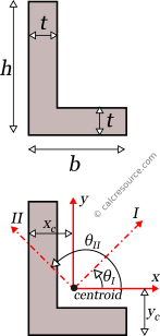
Types of Angle Steel

Equal vs. Unequal angle steel configurations
Equal Leg Angles
Both legs have the same length, providing uniform strength in both directions. Common sizes range from 20×20mm to 200×200mm. Ideal for general structural applications.
- Symmetric load distribution
- Easier connection design
- Standard in most steel specifications
Unequal Leg Angles
One leg is longer than the other, providing different bending resistance in each direction. Used for specialized applications requiring asymmetric strength.
- Optimized for directional loads
- Material efficiency for specific applications
- Common in architectural applications
Hot Rolled Angles
Manufactured through hot rolling process, providing excellent structural properties and weldability. Most common type for structural applications.
- Superior mechanical properties
- Excellent weldability
- Wide range of sizes available
Cold Formed Angles
Formed at room temperature from flat steel sheets. Typically used for lighter structural applications and where precise dimensions are required.
- Precise dimensional tolerance
- Smooth surface finish
- Cost-effective for light applications
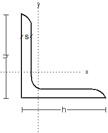
Key Properties and Dimensions
Angle steel cross-section showing key dimensional parameters
Essential Dimensional Parameters
| Symbol | Parameter | Description | Unit |
|---|---|---|---|
| A | Leg Length (Long) | Length of the longer leg | mm |
| B | Leg Length (Short) | Length of the shorter leg | mm |
| t | Thickness | Thickness of the angle material | mm |
| r | Root Radius | Internal radius at the corner | mm |
| Area | Cross-sectional Area | Total area of the cross-section | cm² |
| Ix | Moment of Inertia (x-axis) | Second moment of area about x-axis | cm⁴ |
| Iy | Moment of Inertia (y-axis) | Second moment of area about y-axis | cm⁴ |
| rx | Radius of Gyration (x-axis) | Radius of gyration about x-axis | cm |
| ry | Radius of Gyration (y-axis) | Radius of gyration about y-axis | cm |
Standard Equal Angle Sizes
| Size (mm) | Thickness (mm) | Weight (kg/m) | Area (cm²) | Ix = Iy (cm⁴) | rx = ry (cm) |
|---|---|---|---|---|---|
| 25×25 | 3 | 1.12 | 1.43 | 1.15 | 0.89 |
| 30×30 | 3 | 1.36 | 1.74 | 1.96 | 1.06 |
| 40×40 | 4 | 2.42 | 3.08 | 5.56 | 1.34 |
| 50×50 | 5 | 3.77 | 4.80 | 11.40 | 1.54 |
| 60×60 | 6 | 5.42 | 6.91 | 21.60 | 1.77 |
| 75×75 | 6 | 6.85 | 8.73 | 41.90 | 2.19 |
| 100×100 | 10 | 14.90 | 19.00 | 171.00 | 3.00 |
| 125×125 | 12 | 22.30 | 28.50 | 392.00 | 3.71 |
| 150×150 | 15 | 33.80 | 43.10 | 804.00 | 4.32 |
| 200×200 | 20 | 59.90 | 76.40 | 2350.00 | 5.54 |
Weight Calculations

Comprehensive steel angle weight reference chart
Weight Calculation Formula
For Equal Leg Angles:
Weight (kg/m) = 0.00785 × t × (2a - t)
Where: t = thickness (mm), a = leg length (mm)
For Unequal Leg Angles:
Weight (kg/m) = 0.00785 × t × (A + B - t)
Where: t = thickness (mm), A = long leg (mm), B = short leg (mm)
Weight Calculation Chart
Quick Calculation Tips
- Always use consistent units (mm for dimensions, kg/m for weight)
- The factor 0.00785 is derived from steel density (7850 kg/m³)
- Consider material grade variations for precise calculations
- Add 10-15% for cutting waste in procurement calculations
- Use our Angle Weight Calculator for instant results
Real-World Applications
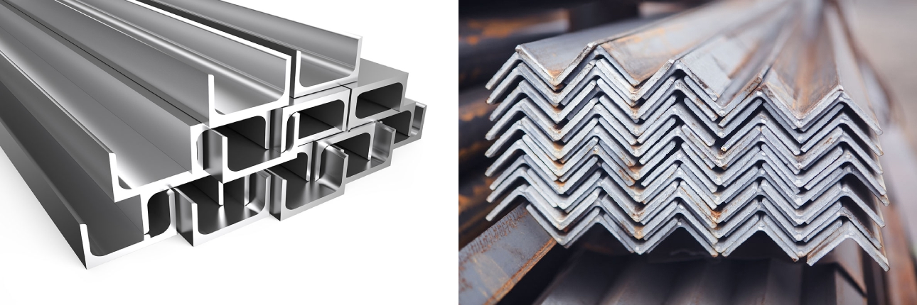
Various applications of steel angles in construction and infrastructure
Building Construction
- Structural framing and bracing
- Lintel supports over openings
- Stair stringers and handrails
- Roof truss connections
- Foundation anchor bolts
Infrastructure
- Bridge construction and repair
- Highway guardrail posts
- Transmission tower legs
- Railway track support
- Utility pole bracing
Industrial Applications
- Equipment support frames
- Conveyor system structures
- Storage rack systems
- Platform and walkway framing
- Machinery mounting brackets
Marine & Offshore
- Ship hull reinforcement
- Offshore platform structures
- Dock and pier construction
- Marine equipment mounting
- Coastal protection structures
Application Selection Criteria
Load Requirements
- Tension vs. compression loads
- Bending moment capacity
- Shear force resistance
- Buckling considerations
Environmental Factors
- Corrosion resistance needs
- Temperature variations
- Exposure conditions
- Maintenance accessibility
Selection Guide
Step-by-Step Selection Process
1. Define Load Requirements
- Calculate maximum expected loads (dead, live, wind, seismic)
- Determine load combinations per applicable codes
- Identify critical load paths and directions
- Consider dynamic and fatigue loads if applicable
2. Geometric Constraints
- Available space for member installation
- Connection requirements and bolt patterns
- Clearance requirements for other systems
- Architectural and aesthetic considerations
3. Material Grade Selection
- Standard grades: A36, A572, A992 (US); S235, S355 (EU)
- Higher strength grades for optimized designs
- Weathering steel for exposed applications
- Galvanized options for corrosion protection
4. Verification and Optimization
- Check member capacity against applied loads
- Verify deflection limits and serviceability
- Optimize for minimum weight or cost
- Review constructability and connection details
Size Selection Chart
Industry Standards
American Standards
- ASTM A36: Standard carbon structural steel
- ASTM A572: High-strength low-alloy steel
- ASTM A992: Structural steel for buildings
- AISC 360: Specification for structural steel buildings
- AISC 341: Seismic provisions
European Standards
- EN 10025: Hot rolled products of structural steels
- EN 10056: Structural steel equal and unequal leg angles
- EN 1993 (Eurocode 3): Design of steel structures
- EN 1090: Execution of steel structures
- S235, S355, S450: Common steel grades
International Standards
- ISO 6316: Steel structures design
- JIS G3101: Japanese industrial standard
- GB/T 700: Chinese national standard
- IS 2062: Indian standard for steel
- AS/NZS 3679: Australian/New Zealand standard
Quality Requirements
- Dimensional tolerance: ±2mm typical
- Surface finish: Mill scale or cleaned
- Straightness: L/1000 maximum bow
- Material certificates: Test reports required
- Welding qualification: Per AWS or equivalent
Engineering Calculations
Essential Design Formulas
Sectional Properties
Area = t × (A + B - t)
Ix = t × A³/12 + t × B × (A/2)²
Iy = t × B³/12 + t × A × (B/2)²
rx = √(Ix/Area)
ry = √(Iy/Area)
Sx = Ix / (A/2)
Capacity Calculations
Tension: Pn = Fy × Ag
Compression: Pn = Fcr × Ag
Bending: Mn = Fy × Sx
Shear: Vn = 0.6 × Fy × Aw
Buckling: Fe = π²E/(KL/r)²
Combined: Pr/Pc + Mr/Mc ≤ 1.0
Load Capacity Chart
Important Design Considerations
- Always apply appropriate safety factors per applicable codes
- Consider effective length factors for compression members
- Account for connection eccentricity in angle applications
- Check local buckling limits for thin-walled sections
- Verify serviceability limits (deflection, vibration)
- Use our Structural Calculators for detailed analysis
Practical Examples
Example 1: Residential Lintel Design
Given:
- Window opening: 2.5m wide
- Load: 15 kN/m (dead + live)
- Material: A36 steel (Fy = 250 MPa)
Solution:
- Maximum moment: M = wL²/8 = 15 × 2.5²/8 = 11.7 kN⋅m
- Required section modulus: S = M/Fy = 11.7×10⁶/250 = 46.8 cm³
- Select: 100×100×10 angle (Sx = 15.1 cm³ each)
- Use double angle (2×15.1 = 30.2 cm³) - adequate with safety factor
Example 2: Transmission Tower Leg
Given:
- Tower height: 30m
- Compression load: 500 kN
- Effective length factor: K = 1.0
- Material: A572 Grade 50 (Fy = 345 MPa)
Solution:
- Assume 150×150×15 angle: A = 43.1 cm², r = 4.32 cm
- Slenderness ratio: KL/r = 1.0×3000/4.32 = 69.4
- Elastic buckling: Fe = π²×200000/69.4² = 410 MPa
- Critical stress: Fcr = 0.658^(Fy/Fe) × Fy = 287 MPa
- Capacity: Pn = 287×43.1 = 1237 kN > 500 kN ✓
Example 3: Tension Brace Design
Given:
- Tension force: 200 kN
- Length: 4m
- Connection: Bolted with 2 bolts
- Material: A36 steel
Solution:
- Gross area required: Ag = T/Fy = 200000/250 = 800 mm²
- Net area (assume 20mm bolt holes): An = 0.85×Ag = 680 mm²
- Try 75×75×8 angle: Ag = 11.4 cm² = 1140 mm² > 800 mm² ✓
- Net area check: An = 1140 - 2×20×8 = 820 mm² > 680 mm² ✓
- Selected size is adequate
Frequently Asked Questions
Share This Resource
Help others access this comprehensive angle steel properties guide:
Bookmark This Essential Resource
This comprehensive guide to angle steel properties serves as your go-to reference for structural engineering calculations, material selection, and design optimization. Whether you're a practicing engineer, student, or construction professional, having quick access to accurate angle steel data is essential for successful projects.
Explore Related Tools: Enhance your structural calculations with our suite of specialized calculators including the Angle Weight Calculator, Beam Design Tools, and Steel Section Calculators.